
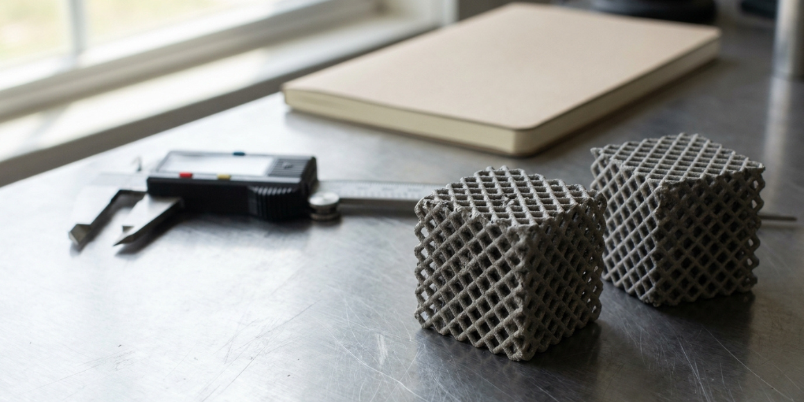
Most of us place a part on the build plate the way it naturally sits, or let an auto-orient tool pick whatever prints fastest with the fewest supports, and we move on.
A 2026 study in Advanced Materials looked at 3D-printed lattices (3D scaffolds of thin struts) in polymer and titanium. It comes from University College London, the University of Sheffield and the European Synchrotron, and one of its findings suggests orientation is worth a second look. We read it and pulled out what matters for product teams, and where we'd be careful about reading too much into it.
The paper's main contribution is a new lattice geometry, the triply-twinned lattice: blocks of struts (called meta-grains, borrowed from twinned grains in metals) mirrored across three perpendicular planes, with the finest version using the smallest blocks. The authors report it as much stiffer and stronger than a conventional lattice using the same amount of material, but we don't rely on the headline numbers. The abstract gives +380% in stiffness and +279% in strength, yet also says "up to three-fold," and UCL's news release calls the same figures "roughly three times better." Read as percentage increases, as the paper does elsewhere, +380% would be about 4.8 times and +279% about 3.8 times. Read as multiples of the baseline, +279% would be about 2.8 times, close to three, but +380% would be 3.8. Neither reading fits every figure. The titanium gains were smaller than the polymer ones: about +270% in stiffness for the finest version, with no titanium strength figure in the text.
The orientation result is a secondary finding from the X-ray analysis, but it's the part most relevant to anyone choosing how to print a load-bearing part, as long as you keep the scope limits below in mind. UCL's news release highlights it as an "immediately practical" finding; the paper's own view is more conditional, as we explain below.
A note on scope: the orientation result we focus on comes from laser powder bed fusion of titanium, and the second example, from the engineering firm Veryst, uses nylon laser sintering. Both are industrial processes. The paper's polymer samples were resin parts printed by stereolithography, all with build and load directions aligned, so they say nothing about orientation. The same principles may apply to filament printing (FDM), but these results don't tell you by how much.
Why orientation changes a part at all
A 3D-printed part isn't the same in every direction. It's built layer by layer, and the way the part sits decides how those layers fall across its most important features.
Veryst, which tests printed lattices, names two complications. Printed geometry is never quite what the CAD model says, and the material itself can behave differently depending on direction (in Veryst's nylon tests, the material's own stiffness did not vary with direction, though part of the strength variation did come from the material). Ignoring build orientation, Veryst warns, can mean unacceptable variation in part performance or unexpected failure.
In metal printing, the study's authors point to a further effect. Downward-facing surfaces tend to come out rough, with partly melted metal called dross, and those spots can start cracks.
What the titanium study found
The researchers printed a titanium (Ti-6Al-4V) lattice of the new triply-twinned design, in its finest meta-grain version. They scanned it with X-ray tomography, including a synchrotron, to map its internal defects and, between compression steps, to see where it cracked. They found two kinds of strut fracture:
- Design-driven fractures (about 60%) started at specific joints in the lattice. A simulation of the perfect design had predicted them.
- Defect-driven fractures (about 40%) started on the underside of horizontal struts in the original orientation, where dross and rough spots had formed. They began at a relatively low strain, about 6.7%, and the simulation of the perfect design missed them completely.
Then they printed the same design again, turned 90° so that the build direction, which had run along the compression axis, was now perpendicular to it, and tested it in compression the same way. The paper's parameter table appears to list the two orientations together in a second build, separate from the print behind the 60/40 split above. We couldn't find whether the original-orientation lattice in that pair had the same 60/40 split.
The upside, and the catch
After the rotation, the paper reports that the share of fractures starting at defects halved. If the starting share was the 40% above, that implies roughly 20% (our calculation, not a figure we found in the paper). That is a finding about where fractures start. It doesn't by itself show that the rotated part was more reliable, and it came with a loss of load capacity (below). Internal porosity was about 2.1–2.2% in both orientations. What changed was the surface: the dross and notches on the most critical struts were substantially reduced.
The catch is that the rotated lattice was about 10% less stiff, about 17% weaker and absorbed about 16% less energy. The authors link this to the shape of the strut cross-sections. Printed struts aren't perfectly round, and turning the part changed how much material sat where the load ran. The overall collapse mode, a diagonal band of failing struts, stayed the same, which the authors take to mean that the lattice design, not the build, sets how it ultimately fails.
One detail we liked is that the team's simulation of the cross-section effect predicted a 27% strength loss, but they measured 17%. The authors suggest the cleaner surface may explain the gap, although their model doesn't capture it. For this design, 17% is the trade-off the researchers actually observed.
The authors present the rotation as a way to mitigate dross-driven failure, and their abstract counts the 50% cut as a gain. Their own guidance for choosing an orientation is more conditional. They say it depends on whether defects on the critical struts cause premature failure or measurable losses of strength or stiffness. If they don't, as the authors report for these as-built lattices, they recommend the orientation that gives the load-bearing struts the most material, and by that test the stronger original orientation would be the better pick here. They also say the overall influence of surface defects on strength is still unresolved. We read the rotation as showing that orientation can move where fractures start, not as a proven fix.

It's not just a metal story
Veryst ran a different kind of test on a nylon lattice printed by selective laser sintering, bending it until it broke. This is company test work, published as a case story rather than a peer-reviewed study, and we couldn't find how many samples it used. Veryst says all the parts for its stiffness tests were printed in the same build, and describes the fatigue parts as built at the same time. Across the orientations tested, which included 0°, 60° and 90° (the page's text doesn't define the angle, but 0° is probably flat on the build plate), stiffness varied by about 15% and strength by about 20%. Veryst found the nylon's own stiffness was essentially the same in every direction, so it attributes most of the stiffness variation to variation in the geometry that was actually produced.
Strength held up between 60° and 90° but dropped sharply below 60°. Veryst attributes that variation to a mix of geometric error and direction-dependent material strength, so it is less clear-cut than the stiffness result.
The fatigue result (failure under repeated loading) was the most striking, with a caveat. Veryst compared only two orientations for fatigue. With the same 500 N peak load, the 0° part was loaded to about 83% of its ultimate strength (the load at which it breaks) and the 60° part to about 68%. Parts built at 0° lasted a few hundred cycles, and parts built at 60° lasted a few thousand. Because the 60° part was about 20% stronger (Veryst's figure), the same load took a smaller share of its strength on every cycle. Veryst ties the order-of-magnitude gap in life to that difference in relative load, and notes that a strength difference of about 20% can drastically affect fatigue life. Veryst also points out that the best orientation for performance can conflict with fitting more parts into a build.
What we don't know yet
Be careful with the numbers. The titanium figures come from one lattice design, the finest-grained version of the new triply-twinned lattice, tested in compression in one direction, so we can't say the result holds for a conventional lattice. The authors caution that their finding that defects had little influence on how the lattice collapsed is specific to these lattices, and that with other materials, densities, processing conditions or designs, defects may matter more. They also say the overall influence of surface defects on strength is still unresolved. The nylon result is also one test structure.
The paper reports four repeat samples for the polymer lattices, but states no repeat count for the titanium tests in the main text, so we don't know how many lattices were tested in each orientation. We also couldn't find how many fractures the 60/40 split rests on. With small numbers, a 10–17% difference could include ordinary print-to-print variation, and a shift from 40% to 20% could be a handful of fractures.
So we'd read this as a reminder that orientation can matter, not as a rule for which way to turn your part.
How we'd decide on orientation
We offer design-for-manufacturing services, so we have a commercial interest in this advice. Our take: orientation is a design decision, not a default setting. For a critical part, we'd ask four things:
- Which features carry the load, and which surfaces face down?
- Do surface defects on the critical features actually cost you strength or life? If testing shows they do, an orientation that avoids them may be worth some lost strength. If not, favour the orientation that gives load-bearing features the most material. In the titanium study the rotation gave up about 17% of strength, 10% of stiffness and 16% of energy absorption, and the authors judged the defects were not materially affecting performance, though they call the overall influence of surface defects on strength unresolved.
- How does the orientation affect build cost and how many parts fit in a run?
- Have we tested real prints in at least two orientations?
A simple way to start is to print at least three copies at each of two orientations, ideally in the same build, so that machine and powder differences don't muddy the comparison. Randomise their positions on the plate so that position doesn't line up with orientation. Test them to failure under the loading your part will actually see. If the part is loaded repeatedly, add a fatigue test as well, since in Veryst's results a roughly 20% strength gap became about an order of magnitude in life. Compare the average and the spread within each orientation. If the gap between orientations is clearly larger than the scatter within each one, orientation is affecting performance and is worth designing around. If the scatter is as large as the gap, you can't tell orientation from ordinary print variation, so print more. Three per group is a minimum, and a spread estimated from so few samples is rough.
Want a second opinion on your part?
If you're planning a physical product and aren't sure how to orient it, or what to test first, our team can help. Take a look at our design for manufacturing services, or get in touch and tell us about your part!


Schedule an initial talk and get to know us better! You already have a basic brief? Send it over so we can have a more productive first meeting!
a meeting
