
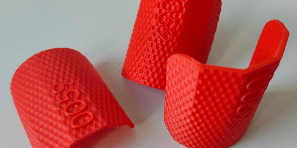
Every additive plastics process - FDM, SLA, SLS - builds parts as stacked layers, and every stacked layer leaves a signature: a staircase effect on curved or angled surfaces, visible ridges on vertical walls, and micro-scale peaks and valleys that catch raking light. The traditional fix has been to engineer the staircase away with finer layer heights, or remove it after the fact through sanding, vapor smoothing, or coating. There is, however, a faster and often cheaper alternative: designing a texture that gives the surface an intentional, dominant visual and tactile pattern, reducing the perceived prominence of the layer signature rather than attempting to remove it entirely.
Why Removing Layer Lines Costs More Than You Think
Post-print surface roughness is measurable, not just a matter of visual judgment. Roughness benchmarking across processes shows how much variance exists in as-printed surfaces, depending on process, material, orientation, and process settings: FDM parts in ASA commonly measure around Ra 22.5 µm and Rz 114.9 µm as printed, MJF PA12 parts run roughly Ra 10–12 µm and Rz 60–70 µm, and Alumide - aluminum-filled PA12 printed via SLS - measures closer to Ra 8 µm and Rz 50.1 µm as printed. SLA resins and select Carbon DLS resins can be far smoother straight off the machine, at roughly Ra 1.2–1.5 µm. These are reference values for specific materials and conditions, not universal parameters for entire technologies - broader industry benchmarking for SLS PA12 shows substantially wider ranges, such as Ra 10–25 µm and Rz 60–140 µm, depending on material variant and finish.
Note: Ra/Rz figures also vary substantially by build orientation and feature geometry - horizontal, side-wall, and downward-facing surfaces on the same SLS part can differ by 8–12 µm, so single-point roughness values should be read as directional benchmarks, not orientation-independent constants. Cross-process reviews confirm that roughness values and their drivers differ significantly between FFF, SLS, vat photopolymerization, and material jetting, and also depend on process parameters and model orientation.
Bringing FDM, SLS, or MJF parts down to a "consumer product" surface typically requires secondary processing. For solvent-compatible materials, chemical vapor smoothing can cut roughness dramatically - acetone vapor exposure has been shown to reduce ABS surface roughness by up to 90% in as little as 10 seconds, and a separate study on chemical post-processing of PLA parts found chloroform immersion achieved roughness reductions of up to 97%. These results shouldn't be read as a universal process recommendation: solvent choice depends on the polymer, and chemical methods require controlled safety conditions, dimensional validation, and an assessment of the impact on part properties.
SLS parts are commonly finished by bead blasting or media tumbling. Depending on material and part requirements, vapor polishing can also be used, provided the material's compatibility with the process medium and the impact on dimensions and functional surfaces have been validated. These processes can meaningfully reduce roughness, but specific values should always be tied to the material, geometry, and finishing method in question - for Alumide specifically, Ra drops from roughly 8 µm as-printed to a 2.5–7 µm range depending on the finishing method applied.
Each of these steps adds cycle time, labor, consumables, and - for chemical methods - HSE overhead and potential impact on mechanical properties. For a production run measured in hundreds or thousands of units, that's a recurring cost stacked onto every part.
Print-parameter tuning, such as line-spacing and ironing settings on PETG parts, can reduce Ra and Rz substantially before any post-processing at all. The method doesn't require a separate finishing station, but it does add print time and requires tighter process control. In one study, ironing alone (without parameter optimization) brought Rz down from 13.95 µm to a 2.15–4.24 µm range depending on settings, and the optimal combination (0.15 mm line spacing, 20% flow) achieved the lowest values recorded, for that specific material and parameter set: Ra 0.37 µm and Rz 2.3 µm - not as a guaranteed outcome across materials or geometries.
Layer-masking texture offers a third path: instead of eliminating roughness, you redesign what the eye and hand perceive, trading a finishing station for a texture map.
How Surface Texture Masks Layer Lines and Defects
The mechanism is straightforward once you separate two things that are easy to conflate: the physical layer artifact and the perceived surface defect. Layer lines are visually disruptive because they're periodic and uniform - the eye is extremely good at detecting regular, repeating patterns, especially on curved or domed surfaces where stair-stepping becomes exaggerated. A designed texture breaks that periodicity. By overlaying an irregular or denser secondary pattern - knurling, stipple, wave, or randomized noise - the texture's spatial frequency dominates the visual field, and the underlying layer steps stop registering as a defect.
Olaf Diegel's Centre for Advanced Materials Manufacturing and Design documented this directly on an SLS powder-bed part: a domed logo surface left smooth showed pronounced, highly visible stair-stepping even after painting, while the same geometry with a texture applied via nTop came off the printer with no visible layer lines at all - same machine, same orientation, texture as the only variable.
Slant3D reports the same effect at FDM production scale, noting that a texture "designed in CAD and then literally printed with the part" can be used specifically "to overwhelm the appearance of the layer lines." The team also points to material-side tricks - such as particulate-filled filament that roughens or speckles the surface - that achieve a similar masking effect without any geometry change at all (method 4, below).
4 Production-Ready Methods to Mask Layer Lines
1. CAD-level displacement mapping
Apply a height map or displacement texture directly to the mesh surface before slicing. This is the method with the highest level of design control, since amplitude, frequency, and pattern are encoded directly in the part's geometry. That makes the texture consistent across design revisions and production batches, provided its minimum feature size is matched to the resolution of the target process, material, and process settings. Purpose-built tools like nTop's texturing module are designed for exactly this workflow on production SLS and DMLS parts. A similar, hybrid approach is available in general-purpose CAD packages - SolidWorks' 3D texture / mesh-modelling module lets you import height maps and textures and generate a mesh from them directly on the model. Where a full CAD environment isn't needed, BumpMesh, a free online tool that works with both CAD and mesh models, offers comparable control at a lower setup cost, letting you apply height maps to selected faces of a model.
2. Slicer-level texture generation
Modern slicers can add texture at the toolpath stage without touching the source CAD file. The "SVG modifier" feature in Orca Slicer and PrusaSlicer lets you map a vector graphic directly onto a model's surface, giving more control over pattern shape and repeatability than purely randomized methods, while keeping the speed typical of slicer-level settings. Bambu Studio's own documentation describes the "Fuzzy Skin" modifier as adding small random movements to the wall path during slicing, turning smooth wall lines into dense, irregular polylines - a mechanism that PrusaSlicer's Knowledge Base confirms for its own implementation, where the perimeter is resampled at a random step size and each new point is shifted inward or outward by a random length bounded by the fuzzy skin thickness setting.
Both slicers govern the effect with the same two parameters - point distance and thickness - producing a textured, layer-line-masking skin on any FDM part with no design rework. This is the fastest method to test and iterate, making it well suited for early DFM trials before committing to a CAD-baked texture.
It is also worth noting Bambu Studio's Scarf Seam feature, which reduces Z-seam visibility by spreading the transition between the start and end of a perimeter over a short section. It does not replace full-surface texturing, but it can complement it where a single seam would be particularly visible. The result should still be validated on the target geometry and material, since performance depends on contour angles and print settings.
3. Build orientation and part angling
Printing at a corner or non-orthogonal angle relative to the build plate changes where and how layer lines fall across curved surfaces, spreading the texture treatment over more of the part and reducing the visibility of stair-stepping on any single face. Combined with a designed surface texture, this is a useful, print-setup-only lever - though not always cost-free: orientation can change support requirements, print time, warping risk, and the quality of downward-facing surfaces.
.png)
Our test blocks printed in three build orientations, showing how the waffle texture pattern shifts across each surface.
4. Material-side texture
Particulate-filled or speckled filaments and resins introduce randomized surface variation from the material itself, breaking up the regularity of layer lines without any geometry or slicer change - useful when a part's CAD and toolpath are otherwise fixed.
Comparing the Four Methods
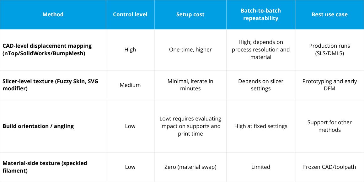
Weighing all four approaches, the right choice mostly comes down to where you are in the design cycle and whether the CAD file is still open for edits:
Texture vs. Finishing: The DFM Trade-Off
Framed as a DFM decision, the math is simple: every micron of roughness removed by sanding, blasting, or vapor smoothing costs machine time, consumables, and often a dedicated finishing station. A designed texture shifts much of that cost upstream into a one-time CAD or slicer setup. The pattern can then be repeated across subsequent parts without a separate manual finishing operation, although its effect on print time, material use, and critical feature quality should be validated for the specific process and geometry. It also redefines what "acceptable quality" means for a visible, unpainted part: rather than chasing a lower Ra number, the target becomes a consistent, intentional surface pattern that reads as a deliberate finish rather than an uncontrolled defect - the same logic industrial designers apply when specifying a bead-blasted or textured injection-molded finish instead of a smooth, mold-polished one.
This isn't a niche technique. Mask-based and pattern-based texturing is already an established engineering discipline in injection molding, where mechanical, chemical, and laser mask-texturing processes intentionally finish surfaces and give them specific functional properties at scale - for example, controlled gloss, in-hand grip, friction, or optical character. Additive manufacturing's advantage is that the same outcome - previously requiring a machined or etched mold - can now be generated computationally and changed between production runs without dedicated texturing tooling. Each change still requires data preparation, validation of minimum feature size, and confirmation of its effect on print time and part properties, making it a meaningful DFM lever for teams running small-batch or frequently revised production - particularly when a part needs a consistent visual finish but has no surfaces that are critical for sealing, fit, or low friction.
FAQ: Layer-Line Masking and Texturing
Does adding texture reduce actual surface roughness, or just hide it visually?
Primarily, it changes the surface's topography and how that topography is perceived - don't assume it will lower Ra or Rz. A designed texture can actually increase measured roughness relative to a smooth reference surface, since it introduces additional, intentional relief. Its benefit is that it replaces an irregular, uncontrolled layer signature with a consistent pattern that reads as a deliberate finish rather than a defect. Where specific Ra/Rz targets matter, they should be measured and qualified independently of visual assessment.
Can texture-masking replace secondary finishing entirely?
For many visible, non-mating, non-sealing surfaces, yes - case studies on SLS and FDM production parts show texture eliminating the need for sanding or painting specifically to hide layer lines. Surfaces requiring tight tolerances, sealing, or bearing contact still need dimensional post-processing regardless of visual texture.
What's the fastest way to test layer-masking texture on an existing design?
Start with a slicer-level feature like Fuzzy Skin to validate whether texture-masking works for your geometry and material before investing in a CAD-baked displacement map - slicer settings can be iterated in minutes without re-exporting the model.
Continue to Part I
This article covered the process-engineering case for texture. Part I, "Surface Texture as a Design Tool," makes the design and UX argument - why leading footwear and electronics brands treat printed texture as a deliberate aesthetic choice rather than a flaw to eliminate. Read Part I.


Schedule an initial talk and get to know us better! You already have a basic brief? Send it over so we can have a more productive first meeting!
a meeting
